

GUIDES & INSIGHTS
Understanding Liquid-Cooling Infrastructure for AI & HPC
As AI and high-performance computing systems increase compute density, cooling becomes more than a component-selection problem.
A liquid-cooled environment may involve facility water systems, coolant distribution units, secondary coolant loops, manifolds, hoses, connection interfaces, sensors, filtration, leak detection and the cooling hardware associated with the compute equipment itself.
Each element has a specific role, but successful infrastructure depends on how those elements work together.
The practical challenge is therefore not simply:
Which cooling product should we use?
A better starting question is:
How should the complete cooling path be structured for this application, and what requirements must each part of that path satisfy?
This guide provides a system-level view of the liquid-cooling infrastructure used around AI and HPC environments and explains where distribution, fluid monitoring and protection fit into the overall architecture.
1. Why AI & HPC Changes the Cooling Conversation
Traditional air cooling remains appropriate for many computing environments. As rack power density and processor heat flux increase, however, moving enough heat through air alone can become increasingly difficult or inefficient.
Liquid can transport substantially more heat than air within a relatively compact physical infrastructure. That makes liquid cooling particularly relevant for high-density compute environments.
But introducing liquid closer to IT equipment also introduces a different set of engineering questions.
The cooling system now needs to account for:
That is why liquid-cooling decisions should begin with the application architecture, not with an isolated component.
2. Think About the Cooling Path as a System
A useful way to understand liquid cooling is to follow the path that heat and coolant take through the infrastructure.
At a simplified level, the architecture can be viewed as:
Facility Cooling → Coolant Distribution → Rack Distribution → Compute Cooling → Heat Return
A facility cooling source removes heat from the overall system.
A coolant distribution system creates the hydraulic and thermal interface between the facility infrastructure and the cooling circuit serving the compute environment.
Distribution hardware then delivers coolant toward individual racks or compute devices.
At the compute level, liquid absorbs heat from processors or other heat-generating components.
The warmed coolant then returns through the system so that the heat can ultimately be rejected.
Although the physical arrangement varies considerably between applications, this system view helps define where major infrastructure functions belong.
The result is not one universal liquid-cooling architecture.
Different OEM platforms, racks, facilities and deployment environments can require different combinations of equipment and controls.
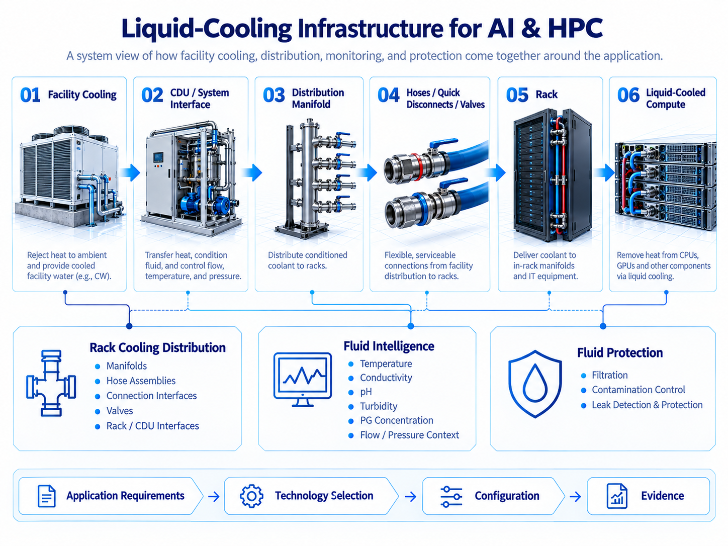
Sections 3-6
3. The Facility Side
The facility side provides the larger thermal environment in which the liquid-cooling system operates.
Depending on the site architecture, this may involve facility water loops, chillers, cooling towers, dry coolers or other heat-rejection infrastructure.
The important point for a liquid-cooling project is not necessarily the specific facility technology. It is the boundary condition presented to the liquid-cooling system.
Relevant information can include:
- available supply-water temperature;
- expected return temperature;
- allowable pressure;
- available flow;
- water quality;
- connection size;
- facility operating conditions;
- redundancy requirements.
These boundary conditions influence what the downstream cooling infrastructure must accomplish.
A cooling architecture designed without understanding the facility interface may appear technically correct at the component level while still being poorly matched to the actual installation.
4. The Role of the Coolant Distribution Unit
A coolant distribution unit, commonly referred to as a CDU, can serve as an important interface between the facility cooling system and the coolant circuit serving IT equipment.
Depending on the architecture, a CDU may perform functions such as:
- heat exchange;
- pumping;
- flow control;
- pressure management;
- temperature control;
- monitoring;
- separation of facility and technology coolant loops.
Not every application uses the same CDU configuration.
The selection depends on the thermal load, facility conditions, coolant requirements, pressure limits, redundancy philosophy and the architecture of the downstream equipment.
For this reason, a CDU should not be evaluated only by nominal cooling capacity.
The interfaces around it matter as well.
Those interfaces lead directly into the distribution architecture.
5. Distribution: Moving Coolant From the System to the Rack
Once coolant leaves the distribution source, it must reach the equipment safely, predictably and with acceptable hydraulic performance.
This is where rack cooling distribution becomes important.
A distribution architecture may include several layers.
Manifolds
Manifolds divide or combine coolant flow between multiple branches.
Depending on the application, manifolds may be located at the system, row, rack or equipment level.
Important design considerations can include:
- number of branches;
- flow distribution;
- pressure drop;
- connection type;
- materials;
- physical mounting;
- serviceability;
- future expansion.
A manifold is therefore more than a collection of ports. Its configuration influences the hydraulic behavior and maintainability of the system.
Hose Assemblies
Hose assemblies provide flexible fluid connections between infrastructure elements.
Their requirements may include:
- internal diameter;
- pressure rating;
- bend radius;
- coolant compatibility;
- temperature range;
- length;
- fitting type;
- routing constraints.
In high-density environments, physical routing can become just as important as hydraulic performance.
Connection Interfaces
Quick disconnects and other connection interfaces allow cooling circuits to be connected and serviced.
Application requirements may include:
- connection size;
- allowable pressure drop;
- operating pressure;
- materials compatibility;
- expected connection cycles;
- spill behavior;
- service access.
Connection interfaces should therefore be selected as part of the broader cooling architecture rather than independently.
Valves and Flow Routing
Valves may be required for isolation, balancing, servicing or control.
The correct valve configuration depends on how the system needs to operate during normal use, maintenance and fault conditions.
Together, manifolds, hoses, connection interfaces and valves create the physical path that delivers coolant from the distribution system toward the rack or compute equipment.
InfraSoma describes this layer as Rack Cooling Distribution.
Explore Rack Cooling Distribution →
6. The Rack and Compute Interface
At the rack level, the cooling infrastructure interfaces with the equipment that is actually generating the heat.
In direct-to-chip systems, liquid typically reaches cold plates associated with processors or other high-heat components.
Other liquid-cooling architectures may use different approaches.
From an infrastructure perspective, the important consideration is the boundary between the facility/distribution system and the compute platform.
Questions can include:
- What coolant conditions does the equipment require?
- What flow is required?
- What pressure limits apply?
- What connections are specified?
- What materials are present in the loop?
- What fluid cleanliness is required?
- What maintenance or service access is needed?
- What evidence or qualification documentation is expected?
Those requirements should flow upstream into decisions about manifolds, hoses, filtration, monitoring and system interfaces.
This is one reason InfraSoma treats OEM cooling platforms as an important application context.
7. Fluid Intelligence: Understanding What Is Happening Inside the Loop
Once liquid becomes part of the thermal infrastructure, knowing the condition of that liquid can become important.
Temperature and flow provide operational information, but coolant condition may involve additional variables.
Depending on the application, useful parameters can include:
- temperature;
- conductivity;
- pH;
- turbidity;
- glycol concentration;
- pressure;
- flow.
Not every system requires every measurement.
The appropriate sensing architecture depends on the coolant, materials, equipment requirements, maintenance strategy and consequences of fluid degradation or contamination.
For example, conductivity may provide useful information about ionic contamination or changes in fluid condition.
pH may help indicate chemical changes that could affect material compatibility.
Turbidity may provide information about suspended contamination.
Where glycol mixtures are used, concentration may also be relevant to understanding the coolant condition.
The objective is not to measure everything.
The objective is to identify which fluid variables actually matter for the specifi
8. Fluid Protection: Keeping the Cooling Circuit Within Acceptable Conditions
Monitoring tells you what may be happening in a coolant loop.
Protection addresses how the system reduces exposure to unwanted conditions.
Two areas are particularly relevant.
Filtration and Contamination Control
Particles and other contaminants can affect valves, pumps, heat exchangers, connection interfaces and small internal cooling passages.
Filtration architecture may therefore need to consider:
- expected contaminant size;
- allowable cleanliness level;
- required flow;
- allowable pressure drop;
- filter location;
- service intervals;
- bypass requirements;
- monitoring of filter condition.
A filter should not simply be added because filtration seems desirable.
The correct filtration strategy depends on the architecture and the actual contamination risk.
Leak Detection and Protection
Bringing liquid close to high-value electronic infrastructure makes leak management an important system-level consideration.
Leak protection may include a combination of:
- leak detection sensors;
- sensing cable;
- local containment;
- isolation valves;
- alarms;
- system-control responses;
- maintenance procedures.
The appropriate architecture depends on the physical environment and on what should happen when a leak is detected.
Detection alone answers:
Is liquid present where it should not be?
A broader protection strategy also asks:
What should the system do next?
InfraSoma describes these functions under Fluid Protection.
9. Distribution, Intelligence and Protection Should Not Be Designed Separately
It is tempting to treat manifolds, sensors and filters as independent product categories.
In practice, they interact.
A filter introduces pressure drop.
A sensor requires an appropriate measurement location.
A flow meter may require straight-run conditions or a specific orientation.
A manifold affects flow distribution.
A leak-detection system depends on where coolant could realistically escape and accumulate.
A quick disconnect influences serviceability and pressure loss.
The architecture therefore benefits from being evaluated as a system.
A useful framework is to think in three connected layers:
Distribution
How does coolant physically move through the application?
Manifolds, hoses, valves, connection interfaces and rack/CDU interfaces.
Intelligence
What information is needed to understand coolant and operating conditions?
Temperature, conductivity, pH, turbidity, glycol concentration, flow, pressure and other relevant measurements.
Protection
How is the system protected against contamination, leaks or abnormal fluid conditions?
Filt
10. There Is No Universal Liquid-Cooling Architecture
Two liquid-cooled data-center projects may use very different infrastructure even when their total thermal loads appear similar.
Differences can come from:
- facility-water conditions;
- rack density;
- OEM equipment requirements;
- coolant chemistry;
- redundancy requirements;
- pressure limitations;
- physical routing;
- maintenance strategy;
- monitoring philosophy;
- environmental conditions;
- project stage;
- qualification requirements.
This is why copying a cooling architecture from one project into another can create problems.
The correct architecture should be based on defined interfaces and operating requirements.
11. Define the Interfaces Before Selecting Components
Before requesting quotations for cooling hardware, define the major system interfaces.
At minimum, consider the following.
Facility Interface
What does the facility provide?
Temperature, flow, pressure, connection size and water conditions.
Distribution Interface
How will coolant move from the cooling source toward the racks?
Define branch requirements, pressure-drop limitations, routing and connection architecture.
Rack Interface
What does each rack or cooling platform require?
Connections, flow, pressure, coolant chemistry and service access.
Fluid Interface
What coolant is being used?
Define chemistry, concentration where applicable, material compatibility and fluid-quality expectations.
Monitoring Interface
What parameters need to be observed?
Identify the measurements that are actually needed for the application.
Protection Interface
What failure or contamination conditions need to be detected or controlled?
Define filtration, leak detection and system-response expectations.
Evidence Interface
What documentation is required?
This may include drawings, material information, technical data, test documentation, certificates or other project-specific evidence.
Clear interfaces make supplier discussions significantly more productive.
12. Move From Architecture to a Practical RFQ
Once the infrastructure is understood at a system level, individual components can be sourced with much greater clarity.
Instead of asking:
Can you quote a manifold?
A better RFQ defines:
- coolant;
- operating temperature;
- pressure;
- required flow;
- number of branches;
- connection interfaces;
- materials;
- physical constraints;
- documentation requirements;
- project timing;
- expected quantity.
The same principle applies to sensors, filters, leak-detection equipment and other elements.
A supplier can respond more effectively when the application boundary is clear.
If you are still defining those requirements, start with our companion guide:
How to Define Requirements for a Liquid-Cooling Application →
13. Think in Systems, Not Isolated Components
Liquid cooling for AI and HPC is ultimately a systems-engineering problem.
The infrastructure must move heat.
But it must also move coolant through the correct physical interfaces, maintain acceptable fluid conditions, provide the right information and protect the surrounding equipment.
That means the strongest architectures consider:
distribution + fluid condition + protection + application requirements
as connected parts of one system.
The goal is not to add complexity.
The goal is to define only the functions the application actually requires and then select technologies that fit those requirements.
Start With the Application
If you are planning, evaluating or sourcing infrastructure for a liquid-cooled AI or HPC application, you do not need to begin with a predetermined product configuration.
Start with the operating conditions, interfaces and project requirements.
InfraSoma can help organize those requirements and identify an appropriate technology, configuration or engineering path.
These three layers should be evaluated together around the requirements of the actual application.
InfraSoma describes this approach as Fluid Intelligence.